FPGA Fire Alarm Control Panel
Completed • March - April 2023Verilog • Vivado Design Suite • Assembly • GTKWave
Collaborators: Cole Weber
For Duke's digital systems class (ECE 350), students are tasked with making a pipelined processor in Verilog that can run on an FPGA, which in our case was a Nexus A7. We debugged our Verilog components with GTKWave, and we then utilized the Vivado Design Suite to synthesize and implement the design of the logic circuits in our Verilog. This processor is then used to make a final project, where my partner and I designed a fire alarm control panel (FACP). Our FACP has a conventional IDC (initiating device circuit), a NAC (notification appliance circuit) and a resettable power circuit. The NAC incorporates System Sensor's 2-wire synchronization and audible silence protocol. The FACP also has a user interface consisting of LEDs for alarm (red), silenced (yellow) and normal (green) status and buttons for silencing and resetting the system.
The official project video recorded by Dr. John Board.
An additional video I filmed testing the FACP.
The processor running the FACP has a pipeline composed of the 5 simple RISC pipeline stages: fetch (F), decode (D), execute (X), memory (M) and write (W). This design necessitated the implementation of stalling in case of a memory load followed by an instruction dependent on the load's result. Bypassing (X/W, X/M and M/W) was also added to increase performance by reducing the need for stalling. The ALU incorporates a two-stage carry-look-ahead adder to allow for a shorter clock period (and thus higher clock frequency). While not used in the FACP, a multiplier/divider utilizing Booth's algorithm and non-restoring division was also included in the processor.
Our conventional IDC consists of initiating devices (smoke detectors, manual pull stations, etc.) connected in parallel with one side of their switches connected to an FPGA Pmod pin and the other side connected to a 3.3 V power source. The side connected to the FPGA Pmod pin is tied to ground using a pull-down resistor in a normal state. When a device triggers, it closes its switch, bringing the side connected to the FPGA's Pmod pin to 3.3 V. The processor then detects this by polling the value of a register dedicated to I/O (as are other inputs, such as the silence and reset buttons).

Circuit diagram for the IDC.
When an alarm condition is detected, the FACP begins modulating the NAC in accordance with the selected synchronization protocol (in our case, we used System Sensor's). The NAC is composed of another Pmod pin being modulated by a change in the I/O register's value. The Pmod pin, which outputs a maximum of 3.3 V, is connected to a relay switching a 24-V power supply for the notification appliances (horns, strobes, etc.).
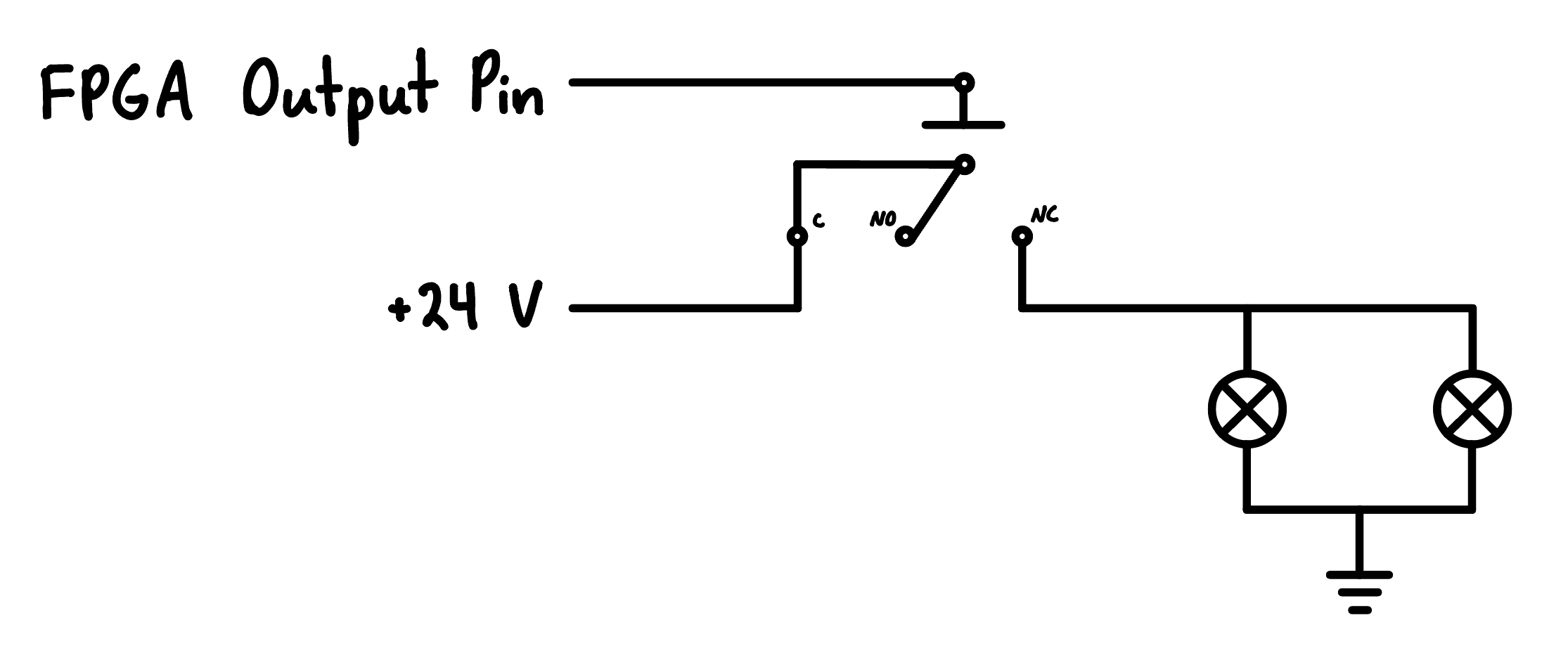
Circuit diagram for the NAC.
As mentioned earlier, the NAC is modulated according to System Sensor's 2-wire synchronization and audible silence protocol. This allows the system to sound the horns in temporal code 3 (and silence them) and keep the strobes flashing in sync over only 2 wires. The protocol's signaling pattern was determined by connecting a System Sensor MDL3 synchronization module I had on hand to an oscilloscope. The pattern was then incorporated into the processor's assembly code as a finite state machine of sorts.
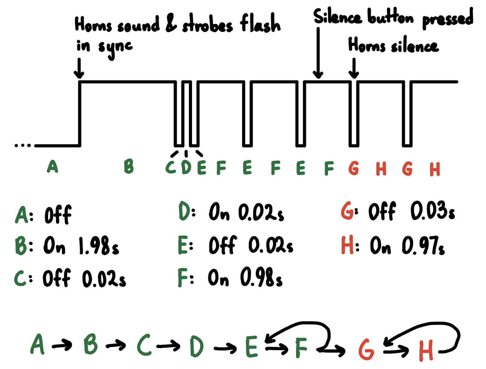
State diagram for the System Sensor 2-wire synchronization and audible silence protocol.
Because the synchronization pattern relies on precise timing, we needed to add timer hardware and assembly instructions to use it into our processor. We decided to create a simple cycle counter, which increments a register every clock cycle after the sct (set cycle timer) instruction is called until it reaches the value provided as an immediate. The bce (branch if cycles elapsed) instruction can then be used to branch to a different part of the program if it has reached the threshold cycle count. Since our processor runs at a fixed frequency, we could use that to calculate how many cycles correspond to the timings for each stage of the synchronization/silencing protocol.
| Instruction | Type | Opcode (ALU Opcode) | Description |
|---|---|---|---|
| and $rd, $rs, $rt | R | 00000 (00010) | $rd = $rs & $rt |
| j T | JI | 00001 | PC = T |
| bne $rd, $rs, N | I | 00010 | If $rd != $rs, PC = PC + 1 + N |
| addi $rd, $rs, $rt | I | 00101 | $rd = $rs + N |
| sct N | JI | 10111 | Start cycle counter with threshold value N |
| bce T | JI | 11000 | If cycle counter is at threshold, PC = T |
Table of the instructions used in the FACP's assembly programming.
Certain initiating devices like conventional smoke detectors require a reset of their power supply to clear an alarm condition and reset their switch. To accommodate this, we connected a Pmod pin to a relay switching the 24-V power supply. When the FACP is reset, it interrupts the power supply for several seconds before reconnecting it and returning the system to a normal status.

Circuit diagram for the resettable power supply.
Had we been given more time for the final project, there were 3 things we wanted to improve on the FACP. First, using an analog-to-digital converter (ADC) for the IDC would have allowed us to implement zone supervision with an end-of-line resistor. This could then detect if the IDC's wiring was cut and indicate a trouble condition on the FACP. Second, we could have implemented interrupts for both input state changes and the timer as opposed to using polling for them. While more architecturally complex, this setup more closely models embedded systems, which are typically the microcontroller of choice for FACPs and other life safety systems. Finally, we wanted to implement a more user-friendly interface using an LCD display to show a readout of the system's status, zone names, etc.
Due to course restrictions, posting the project's Verilog or assembly code publicly on GitHub is a violation of the Duke Community Standard. However, I would be more than happy to show and discuss this project's underlying work one-on-one.